Understanding Solar PV String Sizing Physics and Voltage Limits
How semiconductor physics and winter temperatures dictate solar string voltage, protecting inverters while maximising annual UK solar generation.
- Written by
- Net Zero Home Scheme editorial team
- Last updated
- Topic
- solar, mcs, regulation
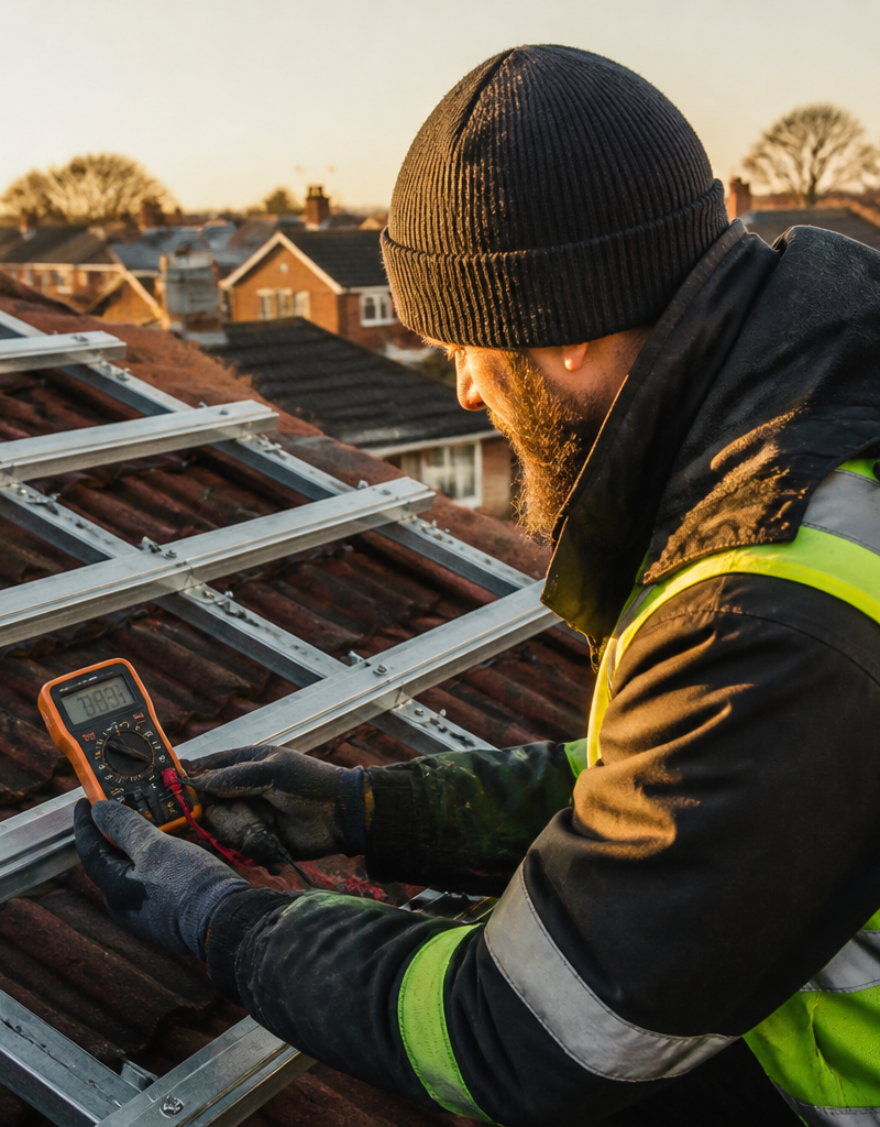
Installing a residential solar photovoltaic (PV) array involves far more than mounting panels on a roof and connecting cables. Behind every well-designed solar installation lies a precise set of electrical calculations dictated by semiconductor physics and environmental extremes. While solar panels are rated by manufacturers under Standard Test Conditions (STC) at an ambient cell temperature of 25°C, real-world UK weather exposes modules to freezing winter mornings as low as -10°C and scorching summer roof temperatures exceeding 60°C.
Because of how silicon cells behave, cold winter weather causes panel voltage to surge significantly. If an installer strings too many panels together in a single circuit, this cold-weather voltage spike can exceed the maximum DC voltage rating of the inverter, damaging internal circuitry and violating UK electrical safety standards. Conversely, undersized strings risk dropping below the minimum operating voltage threshold during hot summer afternoons, causing generation loss. Understanding these thermal and electrical physics is essential for delivering safe, long-lasting solar systems.
The physics of solar cell temperature coefficients
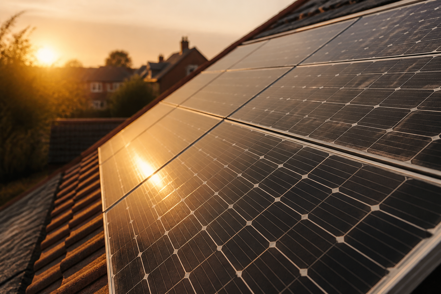
At the atomic level, solar PV panels generate electricity when photons from sunlight strike silicon semiconductors, knocking electrons free to create an electrical current. The open-circuit voltage (Voc) produced by a solar cell depends directly on its internal semiconductor bandgap energy and charge carrier recombination rates, both of which are strongly temperature-dependent.
As the temperature of the silicon cell decreases, the bandgap energy widens slightly and thermal agitation of charge carriers drops. This enables the cell to establish a higher electrical potential across its PN junction, increasing its output voltage. Manufacturers publish this relationship as the temperature coefficient of open-circuit voltage (denoted as beta Voc or %/°C). For standard monocrystalline silicon panels, this coefficient typically ranges from -0.26% to -0.35% per degree Celsius.
Consider a typical 430W monocrystalline panel with a rated STC open-circuit voltage of 38.0V at 25°C and a temperature coefficient of -0.30%/°C. On a freezing January morning in the UK when the roof temperature drops to -10°C, the cell temperature sits 35°C below the standard test baseline. Multiplying this 35°C difference by -0.30%/°C yields a 10.5 percent voltage increase. As a result, the individual panel voltage rises from 38.0V to 42.0V.
When panels are wired in series to form a string, their individual voltages add together. A string of 12 such panels generates an open-circuit voltage of 456V under standard laboratory conditions. On that freezing January morning, however, the string voltage surges to 504V. If the installer had configured a string of 15 panels, the laboratory voltage of 570V would rise to 630V in sub-zero conditions, breaching standard single-phase electrical limits.
BS 7671 and MCS string calculation rules
To prevent catastrophic electrical failures, UK installation standards set strict legal and technical constraints on string design. Under BS 7671:2018+A2:2022 (IET Wiring Regulations Section 712) and the Microgeneration Certification Scheme (MCS) installer standard MIS 3002, installers must calculate array voltages based on the maximum open-circuit voltage expected at the lowest design ambient temperature, standardised across the UK at -10°C.
Most single-phase residential solar inverters installed in the UK carry a maximum allowable DC input voltage rating of 550V or 600V. Exceeding this threshold carries severe technical and safety consequences:
- Equipment failure: Voltage spikes beyond 600V break down the dielectric insulation in internal capacitors and destroy power semiconductor switches within the inverter.
- Voided warranties: Inverters maintain internal fault logs that record peak DC voltages. An overvoltage event provides irreversible evidence that invalidates manufacturer warranties.
- Safety hazards: DC isolators, cables and connectors certified for 600V DC face insulation breakdown, increasing fire and electrical arc risks.
Conversely, summer physics impose the opposite constraint. Under strong summer sunlight at an ambient temperature of 28°C, dark silicon roof tiles often reach cell temperatures of 55°C to 60°C. High temperatures reduce the Maximum Power Point voltage (Vmpp) by roughly 0.35 percent per degree Celsius above 25°C. If a solar string is configured with too few panels, its combined summer operating voltage can fall below the inverter's minimum Maximum Power Point Tracking (MPPT) voltage window, which typically starts between 80V and 120V. When string voltage drops below this floor, the inverter drops out of tracking mode or shuts down entirely during peak sunlight hours.
String sizing parameters and safety thresholds
To illustrate how thermal swings alter string performance, the following table details calculated voltages across typical UK installation scenarios using standard 430W modules with a Voc of 38.0V and a Vmpp of 31.5V.
| System Configuration | Standard Baseline (25°C Cell) | Winter Peak (-10°C Cell) | Summer Floor (60°C Cell) | Operational Status |
|---|---|---|---|---|
| Single Module Voc | 38.0 V | 42.0 V | 34.0 V | Base module voltage rating |
| Single Module Vmpp | 31.5 V | 34.8 V | 27.6 V | Operating voltage under load |
| 10-Module String Voc | 380.0 V | 420.0 V | 340.0 V | Safe operation on 550V or 600V inverter |
| 12-Module String Voc | 456.0 V | 504.0 V | 408.0 V | Optimal design window for 600V inverter |
| 15-Module String Voc | 570.0 V | 630.0 V | 510.0 V | Overvoltage fault; breaches 600V limit |
| 4-Module Short String Vmpp | 126.0 V | 139.2 V | 110.4 V | Marginal performance; risks summer drop-out |
Economics, trade-offs and alternative architectures
When designing a residential array, installers must weigh voltage boundaries against roof dimensions, shading constraints and hardware costs. UK householders generally encounter three primary architectural choices:
- Dual MPPT String Inverters: Modern string inverters usually feature two independent MPPT inputs. Rather than placing 14 panels into a single risky 14-panel string, the installer splits the array into two 7-panel strings. This keeps winter Voc around 294V, comfortably below the 600V maximum limit while remaining safely above the summer MPPT threshold. Dual string inverters offer high central efficiency (typically 97 to 98 percent) at the lowest equipment cost.
- DC Optimisers: Adding DC optimisers (such as SolarEdge systems) behind each module regulates panel-level output while maintaining fixed string voltage at the inverter. This allows longer strings on complex roofs without exceeding DC voltage caps, but adds £300 to £600 to system costs.
- Microinverters: Microinverters (such as Enphase systems) convert DC power to 230V AC directly behind each solar panel, eliminating high-voltage DC roof strings entirely. Roof cabling operates at low SELV voltages, making string sizing calculations unnecessary. However, microinverters increase hardware costs by £400 to £900 on a typical 4kW array and locate power electronics on the hot roof where long-term thermal stress occurs.
What this means for you
For UK homeowners investing in rooftop renewables, verifying that your installer has completed formal string voltage calculations is a crucial quality check. Ensure your written quotation includes detailed MCS-compliant design sheets demonstrating that peak winter open-circuit voltages remain below your chosen inverter's DC input rating.
If you are planning to decarbonise your property with solar panels, home battery storage or an air source heat pump, the Net Zero Home Scheme provides UK employees with access to accredited installers offering member pricing alongside transparent, high-specification system engineering.
Frequently asked questions
What is the maximum DC voltage allowed on UK home solar installations?
Under BS 7671 electrical regulations, residential single-phase solar PV arrays typically operate up to a maximum limit of 600V DC. Most single-phase residential string inverters specify a maximum allowable input limit of 550V or 600V DC to protect internal components.
Why do solar panels generate higher voltage in sub-zero weather?
Solar panels use silicon semiconductors whose electrical efficiency improves in cold temperatures. Lower cell temperatures reduce electron thermal agitation and recombination, allowing the cell to build a stronger voltage potential across its PN junction, increasing open-circuit voltage by about 0.3 percent per degree Celsius drop.
How do I know if my solar array has been sized correctly?
An MCS-certified installer must provide a detailed system design calculation showing the minimum and maximum expected DC string voltages against the inverter manufacturer's specified MPPT voltage range and absolute maximum DC input voltage.
Sources
- MIS 3002: Requirements for MCS Contractors Undertaking Solar PV Installations, MCS Certified
- BS 7671:2018+A2:2022 Requirements for Electrical Installations, Institution of Engineering and Technology