Solar PV Shading Physics: Bypass Diodes, Optimisers and Yields
We examine four common beliefs about solar panel shading, explaining how bypass diodes, string dynamics and DC optimisers affect real-world UK solar yields.
- Written by
- Net Zero Home Scheme editorial team
- Last updated
- Topic
- solar, energy efficiency, home energy
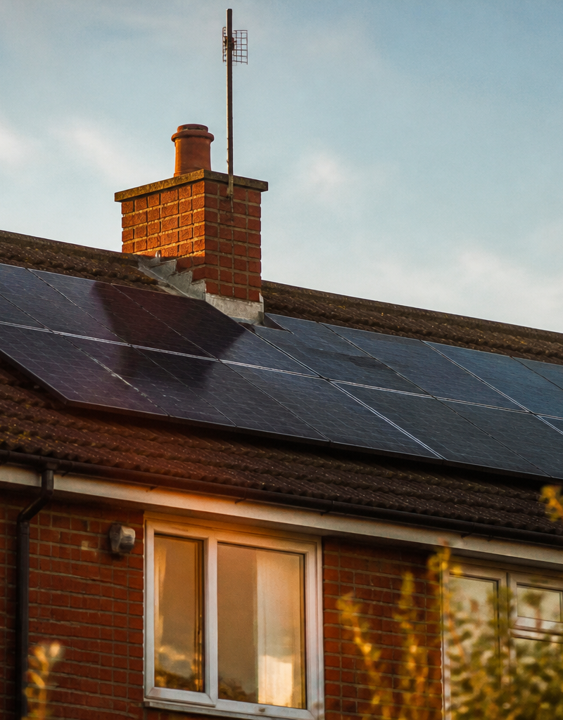
According to official data from the Microgeneration Certification Scheme (MCS), the UK reached over 1.4 million accredited solar PV installations by late 2024. However, shading from chimneys, dormers, satellite dishes, and nearby trees remains one of the largest real-world causes of array underperformance. Under MCS Standard MIS 3002, installers must calculate a shading factor (known as the SF value) to estimate annual generation accurately.
Despite mandatory calculations, widespread misunderstandings persist about how shade interacts with photovoltaic cells, inverter electronics, and system safety. Here, we evaluate four common beliefs against electrical physics and operational performance data to separate real yield risks from unnecessary hardware expense.
Belief 1: A Shadow on One Panel Disables the Entire Array
Historically, solar installations relied on simple series-connected strings where a single shaded cell could severely choke the performance of an entire string of panels. Because silicon solar cells in a standard panel are wired in series, the electric current passing through the string is limited by the cell generating the lowest current. If shade reduces current generation in one cell by 80%, the flow of electrons through every connected cell in that string drops to match it, similar to a crimp in a garden hose.
However, modern photovoltaic systems do not collapse completely when a single panel experiences shade. Monocrystalline modules manufactured today use half-cut cell architecture. Instead of 60 full-sized cells, a standard 400 W module contains 108 or 120 half-cut cells split into two parallel upper and lower sections.
This physical split means that if a shadow falls across the lower half of a panel, the upper half continues to operate at full current capacity. Furthermore, modern string inverters use advanced Maximum Power Point Tracking (MPPT) algorithms. Inverter MPPT sweeps the electrical curve multiple times per minute to find the optimal voltage and current balance, allowing unshaded panels in the string to maintain high output even when individual panels operate at reduced current.
Belief 2: Bypass Diodes Prevent Power Loss Under Partial Shade
To prevent shaded cells from blocking current entirely, module manufacturers integrate silicon bypass diodes into the junction box on the back of every panel. A standard domestic panel contains three bypass diodes, dividing the module into three vertical sub-strings of cells.
When shade falls on a sub-string, its internal resistance increases and it becomes reverse-biased. The bypass diode activates, routing the electrical current around that specific sub-string so the rest of the array can keep conducting power.
While bypass diodes successfully prevent a complete string shutdown, they do not eliminate power loss:
- Voltage drop: Activating a single bypass diode bypasses one-third of the panel's cells, dropping the panel's DC voltage output by approximately 11 to 13 volts.
- MPPT voltage limits: A standard residential string inverter requires a minimum DC input voltage, often between 80 V and 120 V, to remain active. If shadows trigger multiple bypass diodes across several panels, the total string voltage can drop below the inverter's minimum operating threshold, causing the inverter to shut down entirely until light conditions improve.
- Resistance losses: When current passes through a bypass diode, it dissipates heat, creating a minor baseline electrical loss within the junction box.
Bypass diodes are an essential protective safety mechanism rather than a total cure for shading losses.
Belief 3: DC Optimisers Always Pay for Themselves on Shaded Roofs
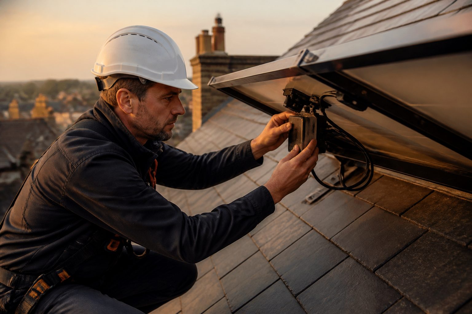
Module-Level Power Electronics (MLPE), such as DC optimisers, attach to individual solar panels to decouple their electrical output from the rest of the string. An optimiser adjusts the voltage and current of its panel in real time, ensuring that a shaded module can output lower power without restricting the current of unshaded modules in the same string.
Many property owners believe that fitting DC optimisers across every panel is essential whenever any shadow is present. However, the economics depend heavily on the severity and duration of the shade.
Energy Saving Trust benchmark data estimates that a 4 kWp domestic solar array in the UK generates between 3,200 kWh and 3,800 kWh annually under unshaded conditions. Adding DC optimisers to a 10-panel array adds between £400 and £700 to upfront installation costs, alongside additional potential failure points on the roof.
If shade is limited to a small soil pipe or narrow chimney casting a shadow for 30 minutes in the late afternoon, the annual energy lost without optimisers may be under 30 kWh, representing less than £8 in lost generation or export value per year. In this scenario, the payback period for full DC optimisation can exceed 25 years, outlasting the warranty of the inverter itself. Selective optimisation, where optimisers are fitted only to the specific panels subject to shade, or dual-MPPT string inverters often achieve far better financial paybacks.
| Technology / Setup | Hardware Cost Adder (10-Panel System) | Shading Mitigation Strategy | Ideal Roof Scenario | Payback & Efficiency Trade-offs |
|---|---|---|---|---|
| Standard String Inverter | Baseline cost (£0 extra) | Uses built-in inverter MPPT algorithms and panel bypass diodes | Unshaded roofs or uniform single-pitch roofs with minor morning shade | Lowest capital cost; drops efficiency if multiple panels are heavily shaded below MPPT voltage |
| String Inverter with Dual MPPT | £50, £150 extra | Separates array into two independent electrical strings | Roofs with two distinct orientations (e.g. East-West) without complex obstruction shading | High efficiency for dual orientations; cannot isolate individual panel shading |
| Selective DC Optimisers | £120, £280 extra | Fitted only to specific shaded panels to bypass current restrictions | Roofs with a single isolated obstruction such as a chimney or vent pipe | Targeted capital expenditure; avoids paying for optimisers across unshaded modules |
| Full Module Optimisation (MLPE) | £400, £700 extra | Adjusts DC voltage and current individually for every panel | Complex multi-pitch roofs with heavy trees, dormers or variable shading | Highest yield recovery; higher upfront cost and more electronics mounted on the roof |
Belief 4: Shading Causes Permanent Hot-Spot Damage to Solar Cells
When a single solar cell within a conventional panel is shaded while the rest of the cells receive intense sunlight, the shaded cell stops producing energy and begins acting as an electrical resistor. The current generated by the bright cells is forced through the resistive shaded cell, converting electrical energy into localized thermal energy. This phenomenon is known as a hot spot.
Historically, severe hot spots could cause localized temperatures to rise above 150 °C, degrading the protective ethylene-vinyl acetate (EVA) film, scorching the backsheet, and in extreme cases causing glass breakage or fire risks.
Modern equipment standards have largely mitigated catastrophic hot-spot risks. Under international standard IEC 61215, all accredited PV modules sold in the UK must undergo strict thermal testing to ensure bypass diodes activate before cell temperatures reach damaging levels.
Furthermore, half-cut cell technology cuts the operating electrical current within each internal circuit in half. Because thermal dissipation is proportional to the square of the current ($P = I^2 R$), halving the cell current reduces thermal energy generation during partial shading by up to 75%. While continuous, severe shading over many years can slightly accelerate localized cell degradation, modern accredited modules rarely suffer structural failure from transient shade.
Employers evaluating ways to help staff manage rising home energy bills can offer targeted support without incurring administrative costs. The Net Zero Home Scheme is completely free for employers to offer and involves no salary sacrifice or payroll administration. Delivered by the team behind The Electric Car Scheme and The Charge Scheme, the benefit connects employees to member pricing on MCS-accredited solar PV, domestic battery storage, and heat pump installations.
Selecting the correct solar technology requires balancing roof geometry against initial equipment costs. For roofs with minimal shading, standard string inverters with half-cut panels offer the fastest payback. Where complex obstacles create moving shadows throughout the day, selective or full DC optimisation protects generation yield and ensures long-term operational efficiency.
Sources
- Microgeneration Certification Scheme Standards, Microgeneration Certification Scheme
- Energy Saving Trust: Guide to Solar Panels, Energy Saving Trust