MCS 012 Solar Mounting Rules and Roof Structural Loading
An explanation of MCS 012 roof mounting standards, wind uplift physics, structural loading limits, and weatherproofing rules for UK solar PV installations.
- Written by
- Net Zero Home Scheme editorial team
- Last updated
- Topic
- solar, regulation, mcs
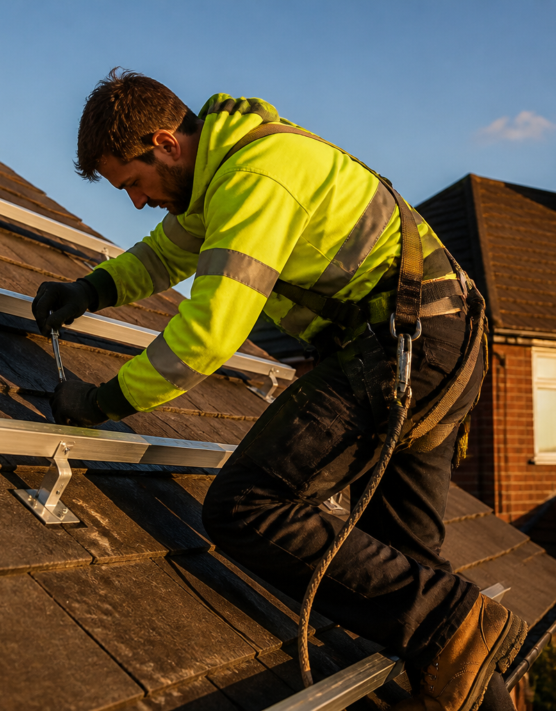
Installing solar photovoltaic (PV) modules on a domestic UK roof involves adding both permanent dead weight and dynamic aerodynamic loads to timber rafters. According to guidelines from the Microgeneration Certification Scheme (MCS), every pitched roof solar installation in England, Scotland, and Wales must comply with MCS 012, the dedicated product and installation standard for solar roof mounting kits. MCS 012 establishes mandatory performance benchmarks for resistance to wind uplift, resistance to snow loads, external fire spread, and weatherproofing integrity.
While conversations around home solar often focus on inverter efficiency ratings and battery capacity, the structural engineering of array mounting determines whether an installation remains secure during gale-force storms and protects the building structure over its 25-year operational lifespan.
What is the MCS 012 structural standard?
MCS 012 is the technical standard that evaluates solar PV roof mounting hardware as an integrated system. Introduced by MCS to prevent structural failures and rain ingress, the standard mandates independent laboratory testing of mounting rails, brackets, roof hooks, and flashing assemblies before they can be certified for UK residential installations.
Under Building Regulations Approved Document A (Structure), any addition to a roof must not compromise the structural integrity of existing rafters, purlins, or wall plates. MCS 012 connects building control regulations with microgeneration engineering by requiring installers to calculate localized wind pressures in accordance with British Standard BS EN 1991-1-4 (Eurocode 1: Actions on structures, Wind actions).
The standard evaluates four primary physical performance areas:
- Wind uplift resistance: The ability of fixings to withstand atmospheric suction forces created as high-velocity wind passes over the roof pitch.
- Downward load capacity: The structural tolerance of brackets and rails to support the combined weight of panels and accumulated winter snow.
- Rain penetration resistance: The effectiveness of slate and tile flashing systems in maintaining a watertight seal around roof penetrations.
- Fire performance: Resistance to external flame spread across roof coverings, tested in accordance with BS EN 13501-5.
How wind uplift and snow load physics affect UK roofs
When strong gales blow across a domestic property, air accelerates over the roof ridge, creating a localized low-pressure envelope above the tiles. According to aerodynamic principles defined in BS EN 1991-1-4, this pressure difference produces a lifting force perpendicular to the roof slope, known as wind uplift.
Wind uplift is not uniformly distributed across a roof. Structural wind testing demonstrates that roof edges, verges, eaves, and ridges experience significantly higher suction turbulence than the central section of the roof pitch. The UK is categorised into distinct wind zones, with coastal areas of northern Scotland, western Wales, and south-west England subject to basic design wind speeds exceeding 26 metres per second. In exposed locations, peak wind uplift forces on a solar array can exceed 1.5 kilonewtons per square metre (kN/m²).
To account for these localized stresses, MCS 012 installation guidelines specify edge zone setback margins. Installers must avoid placing solar panels within a perimeter zone, typically between 300 millimetres and 500 millimetres from the roof edges, verges, and ridge, unless specialized high-density bracket spacing is engineered into the system.
Snow loading creates the opposite mechanical force. A typical 400-watt solar panel weighs between 20 and 22 kilograms, adding a continuous dead load of roughly 10 to 12 kilograms per square metre. However, wet snow accumulation can add an additional 1.0 to 1.5 kN/m² of downward force. In roof spaces constructed with lightweight timber trusses, installers must confirm that the total dead load and winter snow load will not cause rafter deflection exceeding span length divided by 360 (L/360), which could damage internal ceilings below.
Roof fixings and installation methods: Hooks, bolts, and flashings
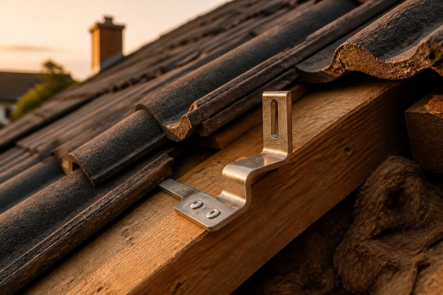
The method of securing mounting rails to timber rafters depends directly on the roof covering material and overall timber condition.
Concrete interlocking tiles
For standard concrete interlocking tiles, installers lift selected tiles to expose the rafter structure. High-grade stainless steel or aluminium roof hooks are screwed into the centre of the rafter using specialized wood screws with a minimum embedment depth of 80 millimetres. The tile directly above the hook stem must be notched on its underside using a diamond blade or replaced with an engineered metal tile flash to ensure the tile lies flat without cracking under heavy snow loads.
Natural and synthetic slates
Natural slate roofs cannot be lifted without removing copper nails. Securing solar arrays to slate requires specialized hanger bolts or double-flashed roof hooks. Installers must fit purpose-made metal flashing plates with EPDM rubber seals around every roof penetration. Direct screw fixings through slates without flashing violate Building Regulations Approved Document C (Resistance to contaminants and moisture).
System structural checklist
The table below outlines the core mechanical criteria and regulatory references required for MCS 012 compliant roof installations.
| Evaluation Area | Compliance Requirement | Applicable UK Standard | Operational Impact |
|---|---|---|---|
| Wind Uplift | Calculation of peak pressure zones | BS EN 1991-1-4 | Prevents array detachment during gale-force storms |
| Rafter Attachment | Minimum 80mm screw embedment | MCS 012 / Eurocode 5 | Ensures mechanical tension loads transfer to timber framing |
| Edge Setbacks | 300mm to 500mm roof edge margins | MCS 012 Installation Guide | Avoids severe turbulent wind vortices at eaves and ridges |
| Weatherproofing | Integrated metal/EPDM flashing | Approved Document C | Eliminates water ingress around tile penetrations |
| Weight Allowance | Maximum rafter deflection L/360 | Approved Document A | Prevents timber sagging under panel weight and snow |
| Fire Resistance | Class BROOF(t4) external fire rating | BS EN 13501-5 | Prevents external fire propagation across roof covering |
What this means for you
For UK homeowners considering solar energy, structural safety is just as essential as system electrical output. Verifying that mounting components carry full MCS 012 certification gives confidence that the installation is engineered to handle local storm conditions and snow loads.
Practical steps to take during the planning phase include:
- Confirming that your chosen installer conducts a visual and mechanical structural assessment of your roof timber prior to installation.
- Checking that your formal quotation specifies MCS 012 certified mounting hardware matching your exact roof tile or slate profile.
- Verifying that panel layout designs maintain recommended setback distances from roof edges, eaves, and ridges.
- Informing your home building insurance provider about the solar PV array, as insurers frequently require confirmation that installations adhere to standard Building Regulations.
Employees exploring green home technology can also look into scheme frameworks such as the Net Zero Home Scheme, which connects workers with accredited installers providing member pricing on solar PV, battery storage, and heat pumps across England, Scotland, and Wales.
Frequently asked questions
Will mounting solar panels void my existing roof warranty?
If installed using MCS 012 certified mounting kits and correct flashing techniques, solar panels should not void standard roof guarantees. However, using uncertified bracket fixings, cracking tiles during installation, or failing to weatherproof timber penetrations can compromise roof warranties. Always ensure your installer provides a dedicated workmanship guarantee covering weatherproofing integrity.
Do I need a structural engineer report before installing solar PV?
On modern timber truss roofs in good condition, standard structural calculation tables provided by MCS 012 manufacturers are usually sufficient for competent installers. However, if your home has an older cut-timber roof, visible rafter sagging, or oversized solar arrays on high buildings, a formal calculation by a chartered structural engineer (IStructE) is required by Building Control.
How are solar panels secured on clay tile or asbestos roofs?
Plain clay tiles require specialised roof hooks designed to span across double-lapped tile layers without applying direct point loads that crack fragile clay. Asbestos cement sheet roofs, found on older outbuildings or garages, must never be drilled or cut under Health and Safety Executive (HSE) safety regulations. Installing solar on asbestos coverings requires non-penetrating clamping systems or full roof replacement before installation.
Sources
- MCS 012 Product and Installation Standard, Microgeneration Certification Scheme
- Building Regulations Approved Document A: Structure, HM Government
- Solar Panels Advice Guide, Energy Saving Trust