Understanding Thermal Bridging in UK Home Retrofits
A practical guide to thermal bridging physics, Psi values, condensation risks, and how to eliminate cold spots during a UK home insulation upgrade.
- Written by
- Net Zero Home Scheme editorial team
- Last updated
- Topic
- insulation, energy efficiency
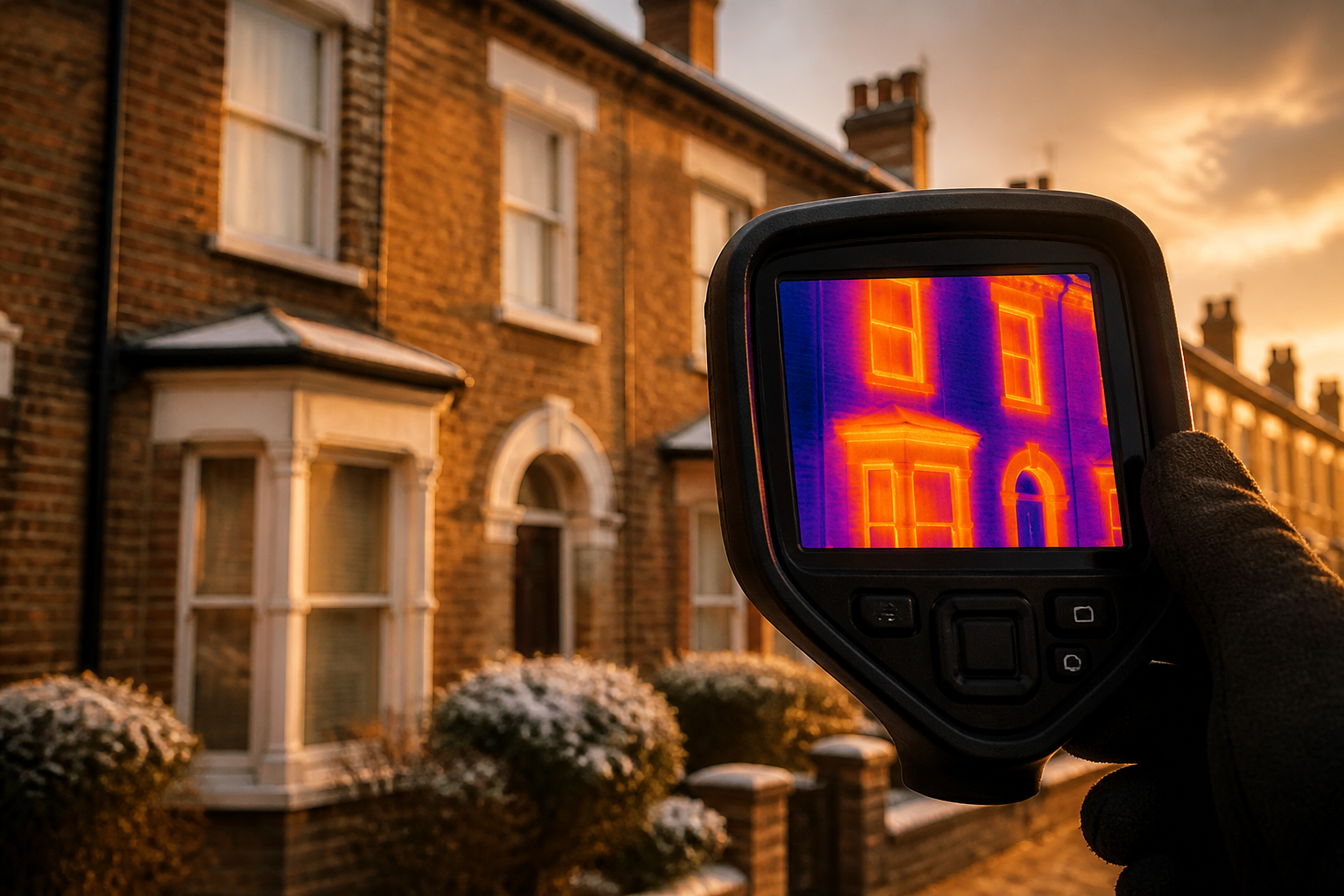
When you upgrade the thermal performance of a British home, adding loft insulation or fitting internal wall insulation appears straightforward on paper. However, heat behaves dynamically, always seeking the path of least resistance to escape from a warm indoor space to the cold external environment. When large areas of external walls or roofs are heavily insulated, localized structural elements that conduct heat easily stand out as heat escape routes. This phenomenon is known as thermal bridging, or cold bridging.
Addressing thermal bridges is a crucial requirement for achieving low energy consumption and preventing structural dampness. In a poorly insulated home, heat escapes fairly evenly across all surfaces. Once high-performance insulation is applied to primary walls, uninsulated junctions, such as window reveals, floor-to-wall interfaces, and steel lintels, become disproportionating drivers of space heating loss and condensation risk.
The physics of thermal bridging and Psi values
Heat loss through a building envelope is measured using two primary metrics. The planar heat loss across a continuous surface, such as a square metre of solid wall, is measured by its U-value in Watts per square metre-Kelvin (W/m²K). Linear heat loss occurring along structural junctions is measured by its Psi value ($
\Psi
$), expressed in Watts per metre-Kelvin (W/mK).
A thermal bridge occurs wherever a material with high thermal conductivity penetrates the insulation layer, or where the geometry of the building creates a mismatch between internal and external surface areas, such as an external wall corner. Common materials responsible for thermal bridges include structural steel (thermal conductivity around 50 W/mK), reinforced concrete (around 2.0 W/mK), and dense brickwork (around 0.77 W/mK), compared to high-performance insulation materials like rigid polyisocyanurate (PIR) board, which has a thermal conductivity as low as 0.022 W/mK.
When heat flows rapidly through a conductive bridge, the temperature of the internal wall surface at that specific junction drops significantly lower than the surrounding insulated walls. If the surface temperature falls below the dew point of the warm, moisture-laden indoor air, water vapor condenses into liquid water.
In building physics, this risk is quantified using the internal surface temperature factor ($f_{Rsi}$). Under UK building standards, including Approved Document L and PAS 2035 design guidance, a minimum $f_{Rsi}$ value of 0.75 must be maintained in residential buildings to prevent surface condensation and the subsequent growth of pathogenic moulds such as Aspergillus niger.
The economics and energy impact of cold bridges
In an uninsulated solid-wall property built before 1919, thermal bridging accounts for roughly 10% to 15% of total fabric heat loss. Because the overall wall U-value is high (typically around 2.1 W/m²K), structural junctions do not significantly alter total space heating requirements.
However, if you apply internal wall insulation (IWI) or external wall insulation (EWI) to lower the wall U-value to 0.30 W/m²K, the relative impact of unaddressed linear thermal bridges changes dramatically. If window reveals, floor joist ends, and party wall junctions are left untreated, thermal bridges can account for up to 30% or more of the home's total remaining fabric heat loss.
According to modelling data from the Energy Saving Trust, an unaddressed set of window reveal thermal bridges in a standard three-bedroom semi-detached home can add between £80 and £140 per year to space heating costs under current energy prices, while simultaneously creating conditions for localized mould growth.
| Junction Location | Typical Unremediated Psi Value (W/mK) | Remediated Psi Value (W/mK) | Common Remediation Approach |
|---|---|---|---|
| Window / Door Reveal | 0.50 | 0.05 | Applying 20mm aerogel or PIR insulation overlay to internal reveals |
| Suspended Timber Floor Junction | 0.32 | 0.08 | Extending perimeter insulation below floor level or wrapping joist ends |
| Solid Wall to Roof Eaves | 0.28 | 0.06 | Overlapping loft insulation continuous with external wall insulation |
| Party Wall Junction | 0.18 | 0.04 | Returning wall insulation 200mm along the party wall surface |
Retrofit trade-offs and practical challenges
Eliminating thermal bridges entirely during a retrofit can present complex structural and architectural challenges. The ideal theoretical solution is a continuous, unbroken perimeter of insulation around the entire thermal envelope. In practice, real-world British housing stock imposes significant limits.
Internal wall insulation reveal limits
When installing internal wall insulation, window reveals present a severe dimensional constraint. Traditional window frames rarely have sufficient depth to accommodate 50mm or 100mm of standard PIR insulation without overlapping the glass or obscuring the window mechanism. Installers must often compromise by using thinner, higher-cost materials like ultra-thin aerogel boards (typically 10mm to 20mm thick) on reveal returns. While aerogel has a thermal conductivity of around 0.015 W/mK, the high material cost represents a genuine trade-off for homeowners on a tight budget.
Joist ends and interstitial condensation
Where suspended timber floor joists sit embedded in solid brick external walls, insulating the internal face of the wall leaves the timber joist ends on the cold side of the insulation layer. Heat from the room no longer reaches the masonry pocket, causing the joist end to run significantly colder in winter. Moisture migrating from the room through the wall structure can condense around the cold timber, creating a high risk of wet rot over extended periods unless vapor control layers or breathable lime plaster systems are meticulously installed in compliance with PAS 2035 retrofitting standards.
Eaves detailing with loft insulation
In traditional pitched roofs, laying 300mm of mineral wool loft insulation across the ceiling joists can accidentally block the eaves ventilation gaps, leading to timber rot in the roof space. Conversely, pulling the insulation back from the eaves to preserve airflow creates a severe thermal bridge directly above the external wall top plate. Retrofit installers must use specialized eaves ventilation baffles to maintain a clear 25mm air path while allowing insulation to extend over the wall cavity plate.
What this means for you
If you are planning major insulation work, such as internal or external wall insulation, treating thermal bridges must be integrated into the initial design rather than treated as an afterthought.
- Insist on PAS 2035 compliance: Ensure your retrofit coordinator carries out a detailed assessment of structural junctions to verify that internal surface temperature factors ($f_{Rsi}$) will remain above 0.75.
- Budget for reveal treatments: When getting quotes for wall insulation, check whether window reveals, door returns, and floor-to-wall interfaces are explicitly included in the scope of work.
- Check ventilation alongside insulation: Preventing condensation requires balancing surface temperature improvements with adequate background ventilation, such as trickle vents or decentralized mechanical ventilation with heat recovery (dMVHR).
If you are evaluating home upgrades, accredited advice and qualified installers are essential to ensure your retrofit performs safely over the long term. The Net Zero Home Scheme provides UK employees with access to accredited installers across England, Scotland, and Wales for home energy improvements.
Frequently asked questions
How do I know if my home has severe thermal bridges?
Common signs of thermal bridging include localized damp patches, dark mould lines running along ceiling borders or around window frames, and cold spots on walls revealed by a thermal imaging camera during winter months.
Can thermal bridging cause mould even if I have loft insulation?
Yes. In fact, adding thick loft insulation without addressing draughts or wall junctions can lower surface temperatures at uninsulated edges, increasing relative humidity locally and triggering mould growth at those specific cold points.
Is external wall insulation better than internal wall insulation for cold bridges?
External wall insulation (EWI) is generally more effective at eliminating thermal bridges because it wraps the building frame in a continuous outer layer. However, EWI still requires detailed attention around roof eaves, window sills, and sub-floor vents to prevent localized cold bridges.